English
 Русский
 العربية
- Introduction
- Ambient Conditions
- Main Technical Data
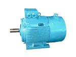
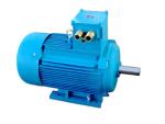
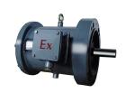
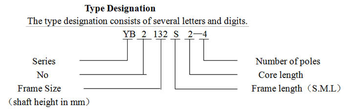
The YB2 series of explosion-proof three-phase induction motors are flame-proof motors that meet advanced international standards. These explosion-proof motors feature high efficiency, high locked-rotor torque, low noise and vibration, and reliable operation. The motor output and mounting comply with IEC standards and GB3836.2 standards for electrical apparatus in explosive situations. the flame-proof feature makes these induction motors ideal for coal mines where methane and coal dust may be present or in factory spaces where flammable gases may be present.


Features:
1. IP55 protection rating.
2. Vertical and horizontal cooling ribs on frame.
3. Ball bearings, small diameter fans, and slot-skewing slopes for low vibration.
4. F class insulation. Above sea level and with standard ambient temperatures, the temperature rise limit of the stator windings is 80K (resistance method). For a frame size of 315L2 and for 4-pole motors with a frame size of 355, the temperature rise limit is 105K.
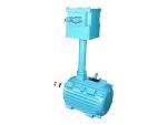
5. The terminal box has three terminals (for single voltage) or six terminals (for double voltages) and is located on the top of the motor. Armoured cable can also be used.
6. The direction of rotation of the motor for frame sizes H63 to 280 and H315 to 355 motors (4 to 10-poles) may be clockwise and anticlockwise. For frame sizes 315 to 355 2-pole motors, the direction of rotation is clockwise as viewed from the shaft extension. If the motor is required to rotate anticlockwise, please specify when ordering.
Ambient Conditions
Ambient air temperature changes with season, but does not exceed 35℃ (underground coal mine) or 40℃ (factory space), and is not lower than -15℃.
Altitude above sea level: up to 1000m.
Note: when ambient air temperature and altitude are different from the above, refer to GB755.
In the wettest month, the monthly-average maximums relative humidity is 90%, and the minimum temperature should not exceed 25℃ in this month (in factory spaces). In the underground coal mine, the highest relative humidity does not exceed 95%.
In underground coal mines (non-excavating conditions) or factories with easy-ignition and explosive gas or steam, the temperature class is T1~T4.
Rated frequency: 50Hz.
Rated voltage: 380V, 660V and 380/660V.
Note: If you have special requirements for frequency, voltage, ambient air temperature and altitude, etc. please specify them when ordering.
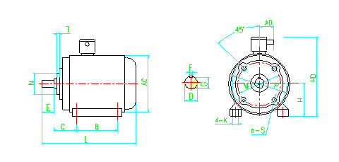
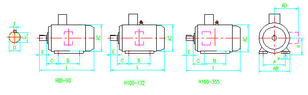
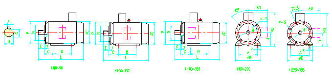
Mounting Arrangement
There are 4 basic mounting arrangements and 10 variant mounting arrangements as shown in the following table:
The B14 motor arrangement features a frame with feet and end-shield with flange (with threaded holes).
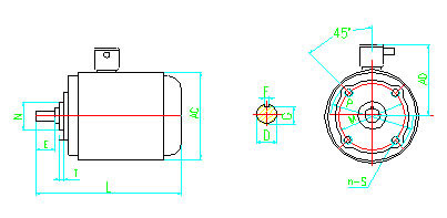
| Frame size | Mounting and overall dimensions | ||||||||||||||||||||
| A | B | C | D | E | F | G | H | K | M | N | P | S | T | n | Pipe thread for cable entry | AB | AC | AD | HD | L | |
| 63M | 100 | 80 | 40 | 11 | 23 | 4 | 8.5 | 63 | 7 | 75 | 60 | 90 | M5 | 2.5 | 4 | M24 × 1.5 | 130 | 150 | 165 | 230 | 270 |
| 71M | 112 | 90 | 45 | 14 | 30 | 5 | 11 | 71 | 85 | 70 | 105 | 140 | 155 | 250 | 300 | ||||||
| 80M | 125 | 100 | 50 | 19 | 40 | 6 | 15.5 | 80 | 10 | 100 | 80 | 120 | M6 | 3 | M30 × 2 | 165 | 165 | 180 | 230 | 330 | |
| 90S | 140 | 56 | 24 | 50 | 8 | 20 | 90 | 115 | 95 | 140 | 180 | 180 | 350 | 360 | |||||||
| 90L | 125 | 385 | |||||||||||||||||||
| 100L | 160 | 140 | 63 | 28 | 60 | 24 | 100 | 12 | 130 | 110 | 160 | M8 | 3.5 | 200 | 205 | 400 | 440 | ||||
| 112M | 190 | 70 | 112 | 245 | 230 | 200 | 420 | 460 | |||||||||||||
| Note: The numerators of fractions in the table give the data for 2-pole motors and the denominators of fractions give the data for motors with more than 2 poles. |
|||||||||||||||||||||
| Frame size | Mounting and overall dimensions | ||||||||||||||
| A | B | C | D | E | F | G | H | K | Pipe thread for cable entry | AB | AC | AD | HD | L | |
| 63M | 100 | 80 | 40 | 11 | 23 | 4 | 8.5 | 63 | 7 | M24 × 1.5 | 130 | 150 | 165 | 230 | 270 |
| 71M | 112 | 90 | 45 | 14 | 30 | 5 | 11 | 71 | 140 | 155 | 250 | 300 | |||
| 80M | 125 | 100 | 50 | 19 | 40 | 6 | 15.5 | 80 | 10 | M30 × 2 | 165 | 165 | 180 | 230 | 330 |
| 90S | 140 | 56 | 24 | 50 | 8 | 20 | 90 | 180 | 180 | 350 | 360 | ||||
| 90L | 125 | 385 | |||||||||||||
| 100L | 160 | 140 | 63 | 28 | 60 | 24 | 100 | 12 | 200 | 205 | 400 | 440 | |||
| 112M | 190 | 70 | 112 | 245 | 230 | 200 | 420 | 460 | |||||||
| 132S | 216 | 89 | 38 | 80 | 10 | 33 | 132 | 280 | 270 | 450 | 510 | ||||
| 132M | 178 | 550 | |||||||||||||
| 160M | 254 | 210 | 108 | 42 | 110 | 12 | 37 | 160 | 15 | M36 × 2 | 330 | 325 | 220 | 520 | 670 |
| 160L | 254 | 710 | |||||||||||||
| 180M | 279 | 241 | 121 | 48 | 14 | 42.5 | 180 | 355 | 360 | 550 | 730 | ||||
| 180L | 279 | 750 | |||||||||||||
| 200L | 318 | 305 | 133 | 55 | 16 | 49 | 200 | 19 | M48 × 2 | 390 | 400 | 250 | 645 | 805 | |
| 225S | 356 | 286 | 149 | 55/60 | 110/140 | 16/18 | 49/53 | 225 | 435 | 450 | 690 | 865 | |||
| 225M | 311 | 860/890 | |||||||||||||
| 250M | 406 | 349 | 168 | 60/65 | 140 | 18 | 53/58 | 250 | 24 | M64 × 2 | 490 | 500 | 300 | 730 | 945 |
| 280S | 457 | 368 | 190 | 65/75 | 18/20 | 58/67.5 | 280 | 545 | 560 | 810 | 1010 | ||||
| 280M | 419 | 1060 | |||||||||||||
| 315S | 508 | 406 | 216 | 65/80 | 140/170 | 18/22 | 58/71 | 315 | 28 | 640 | 630 | 400 | 1020 | 1320/1350 | |
| 315M | 457 | 1350/1380 | |||||||||||||
| 315L | 508 | 1490/1520 | |||||||||||||
| 355S | 610 | 500 | 254 | 75/95 | 20/25 | 67.5/86 | 355 | 28 | M72 × 2 | 740 | 750 | 500 | 1080 | 1570 | |
| 355M | 560 | 1650 | |||||||||||||
| 355L | 630 | 1750 | |||||||||||||
| Note: The numerators of fractions in the table give the data for 2-pole motors and the denominators of fractions give the data for motors with more than 2 poles. | |||||||||||||||
| Frame size | Mounting and overall dimensions | |||||||||||||||||||||||||
| A | B | C | D | E | F | G | H | K | M | N | P | S | T | n | Pipe thread for cable entry | AB | AC | AD | HD | L | ||||||
| 80 | 125 | 100 | 50 | 19 | 40 | 6 | 15.5 | 80 | 10 | 165 | 130 | 200 | 12 | 3.5 | 4 | M30 × 2 | 165 | 165 | 180 | 320 | 330 | |||||
| 90S | 140 | 56 | 24 | 50 | 8 | 20 | 90 | 180 | 180 | 350 | 360 | |||||||||||||||
| 90L | 125 | 385 | ||||||||||||||||||||||||
| 100L | 160 | 140 | 63 | 28 | 60 | 24 | 100 | 12 | 215 | 180 | 250 | 15 | 4 | 205 | 205 | 400 | 440 | |||||||||
| 112M | 190 | 70 | 112 | 245 | 230 | 200 | 420 | 460 | ||||||||||||||||||
| 132S | 216 | 89 | 38 | 80 | 10 | 33 | 132 | 265 | 230 | 300 | 280 | 270 | 450 | 510 | ||||||||||||
| 132M | 178 | 550 | ||||||||||||||||||||||||
| 160M | 254 | 210 | 108 | 42 | 110 | 12 | 37 | 160 | 15 | 300 | 250 | 350 | 19 | 5 | M36 × 2 | 330 | 325 | 220 | 520 | 670 | ||||||
| 160L | 254 | 710 | ||||||||||||||||||||||||
| 180M | 279 | 241 | 121 | 48 | 14 | 42.5 | 180 | 355 | 360 | 550 | 730 | |||||||||||||||
| 180L | 279 | 750 | ||||||||||||||||||||||||
| 200L | 318 | 305 | 133 | 55 | 16 | 49 | 200 | 19 | 350 | 300 | 400 | M48 × 2 | 390 | 400 | 250 | 645 | 805 | |||||||||
| 225S | 356 | 286 | 149 | 55/60 | 110/140 | 16/18 | 49/53 | 225 | 400 | 350 | 450 | 8 | 435 | 450 | 690 | 865 | ||||||||||
| 225M | 311 | 860/890 | ||||||||||||||||||||||||
| 250M | 406 | 349 | 168 | 60/65 | 140 | 18 | 53/58 | 250 | 24 | 500 | 450 | 550 | M64 × 2 | 490 | 500 | 300 | 730 | 945 | ||||||||
| 280S | 457 | 368 | 190 | 65/75 | 18/20 | 58/67.5 | 280 | 545 | 565 | 810 | 1010 | |||||||||||||||
| 280M | 419 | 1060 | ||||||||||||||||||||||||
| 315S | 508 | 406 | 216 | 65/80 | 140/170 | 18/22 | 58/71 | 315 | 28 | 600 | 550 | 660 | 24 | 6 | 640 | 630 | 400 | 1020 | 1320/1350 | |||||||
| 315M | 457 | 1350/1380 | ||||||||||||||||||||||||
| 315L | 508 | 1490/1520 | ||||||||||||||||||||||||
| 355S | 610 | 500 | 254 | 75/95 | 20/25 | 67.5/86 | 355 | 740 | 680 | 800 | M72 × 2 | 740 | 750 | 500 | 1080 | 1570 | ||||||||||
| 355M | 560 | 165 | ||||||||||||||||||||||||
| 355L | 630 | 1750 | ||||||||||||||||||||||||
| Note: The numerators of fractions in the table give the data for 2-pole motors and the denominators of fractions give the data for motors with more than 2 poles. | 1650 |
|||||||||||||||||||||||||
| Frame size | Mounting and overall dimensions | ||||||||||||||
| D | E | F | G | M | N | P | S | T | n | Pipe thread for cable entry | AC | AD | L | ||
| B5 | V1 | ||||||||||||||
| 63 | 11 | 23 | 4 | 8.5 | 115 | 95 | 140 | 10 | 3 | 4 | M24 × 1.5 | 130 | 170 | 270 | 310 |
| 71 | 14 | 30 | 5 | 11 | 130 | 110 | 160 | 145 | 300 | 340 | |||||
| 80 | 19 | 40 | 6 | 15.5 | 165 | 130 | 200 | 12 | 3.5 | M30 × 2 | 165 | 240 | 330 | 375 | |
| 90S | 24 | 50 | 8 | 20 | 180 | 260 | 360 | 405 | |||||||
| 90L | 385 | 430 | |||||||||||||
| 100L | 28 | 60 | 24 | 215 | 180 | 250 | 15 | 4 | 205 | 300 | 440 | 485 | |||
| 112M | M36 × 2 | 230 | 310 | 460 | 520 | ||||||||||
| 132S | 38 | 80 | 10 | 33 | 265 | 230 | 300 | 270 | 320 | 510 | 590 | ||||
| 132M | 550 | 630 | |||||||||||||
| 160M | 42 | 110 | 12 | 37 | 300 | 250 | 350 | 19 | 5 | 325 | 360 | 670 | 730 | ||
| 160L | M48 × 2 | 710 | 770 | ||||||||||||
| 180M | 48 | 14 | 42.5 | 360 | 370 | 730 | 800 | ||||||||
| 180L | 750 | 820 | |||||||||||||
| 200L | 55 | 16 | 49 | 350 | 300 | 400 | 400 | 445 | 805 | 875 | |||||
| 225S | 55/60 | 110/140 | 16/18 | 49/53 | 400 | 350 | 450 | 8 | M64 × 2 | 450 | 465 | 865 | 935 | ||
| 225M | 860/890 | 930/960 | |||||||||||||
| 250M | 60/65 | 140 | 18 | 53/58 | 500 | 450 | 550 | 500 | 500 | 945 | 1035 | ||||
| 280S | 65/75 | 18/20 | 58/67.5 | 560 | 550 | 1010 | 1100 | ||||||||
| 280M | 1060 | 1150 | |||||||||||||
| 315S | 65/80 | 140/170 | 18/22 | 58/71 | 600 | 550 | 660 | 24 | 6 | 630 | 705 | _- | 1340/1370 | ||
| 315M | 1420/1450 | ||||||||||||||
| 315L | 1510/1540 | ||||||||||||||
| 355S | 75/95 | 20/25 | 67.5/86 | 740 | 680 | 800 | M72 × 2 | 750 | 725 | 1600 | |||||
| 355M | |||||||||||||||
| 355L | 1780 | ||||||||||||||